


| Name | 2008 S&S Coiled Tubing Unit |
| Code | 31582140 |
| Type | Standard |
| Brand | S and S |
| Category | Rigs |
| subcategory | Coil Tubing Units |
| Price | $325,000.00 |
| Unit | Each (Each) |
| In Stock | No |
| Location | Houston, TX |
| Type | Sold |
| Short Description | *THIS ITEM HAS BEEN SOLD - FOR OTHER OPTIONS PLEASE CALL 844-475-2060 OR CLICK THE ICON BELOW FOR INSTANT CHAT! |
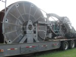
2008 S&S Coiled Tubing Unit
Type: Used
Condition: Very Good
Location: Houston, TX
2008 S&S Coiled Tubing Unit | Details
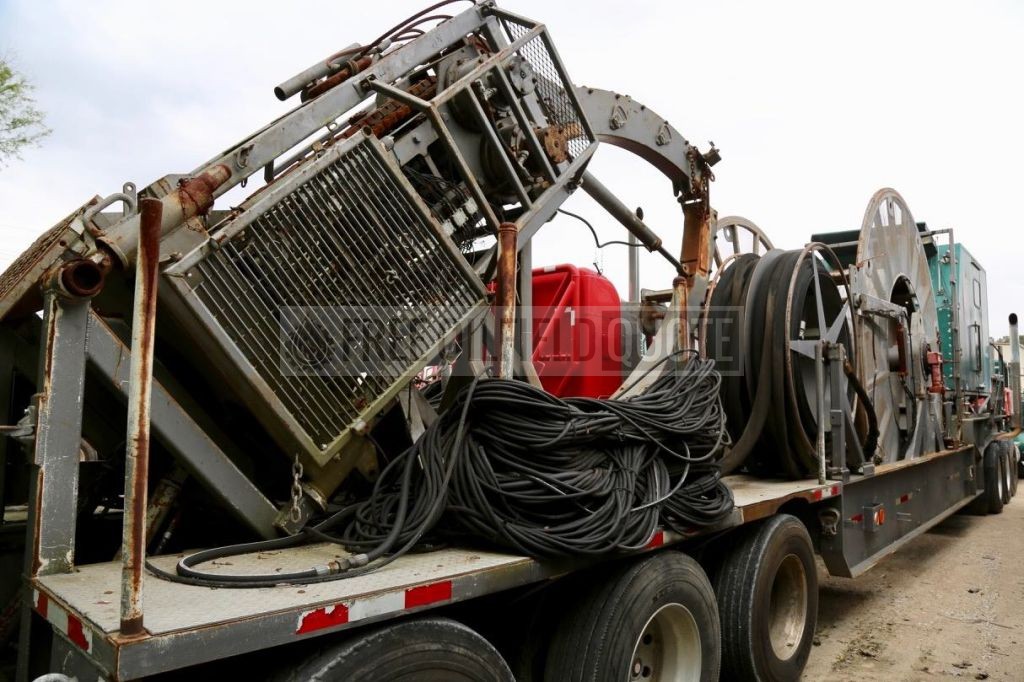
TRAILER MOUNTED HIGH CAPACITY COILED TUBING UNIT MODEL TT-100-HC
1.0 DESCRIPTION
This specification covers the requirements of design, fabrication and testing of a Trailer Mounted Coiled Tubing Unit suitable for onshore use.
2.0 SCOPE OF SUPPLY
Stewart & Stevenson is responsible for the supply of a Trailer Mounted Coiled Tubing Unit including the following:
- One (1) Drop-through style Reel Trailer with Injector Tilt Mount
- One (1) Wet kit power pack
- One (1) Control cabin
- One (1) Tubing reel assembly
- One (1) Injector Head assembly
- One (1) Hose reel and hose assembly
- One (1) Unitization and completion
NOTE: THIS UNIT SHALL BE DRESSED FOR 1.75” TUBING
HIGH CAPACITY TRAILER PACKAGE – DROP THROUGH REEL
1.0 TRAILER ASSEMBLY
The Trailer Assembly will be a heavy-duty drop deck trailer with the following features:
- High strength T-1 steel beam trailer
- 18” Minimum ground clearance (not including drip pan)
- 13’6” Maximum height
- 45’ Maximum length
- Removable drip pan installed underneath reel
- Holland Mark V landing legs
- Axles (3 each) 25,000 lb. capacity each oil bath. Axles to have dual disc, ten (10) hole bud, and polished aluminum wheels.
- Air brake system
- Grated deck flooring
- 2 in. SAE king pin with 3/8 rub plate
- Lights, stop/turn armored clearance
- Mud flaps
- Rear bumper
- Running lights for highway use
- Fold down walkway - driver’s side cabin with ladder and handrails
- 4 ft wide fold up platform with ladder and handrails to access passenger side cabin door
- Two (2) 5 ft wide fold down work platforms on either side of the work reel mounted inside the trailer flange
- Reflective Tape
- Ladder rack
- Mounting brackets for all components including reel assembly, control cabin assembly, etc.
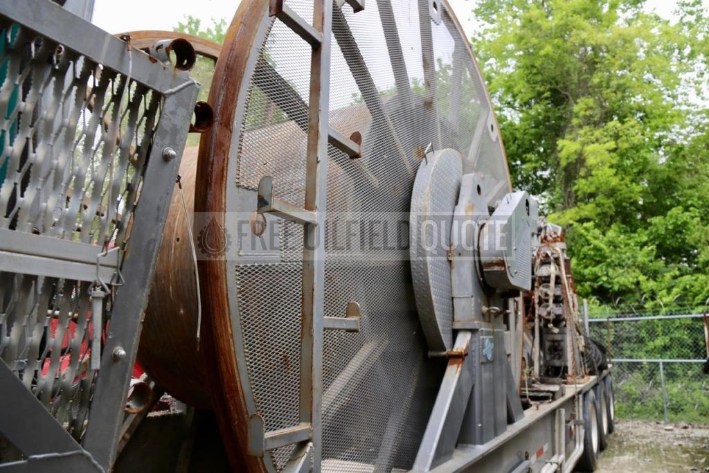
2.0 REEL ASSEMBLY
Installed on this unit will be a Reel Unit Package. This package will be a drop through type reel. Basic specifications of the unit are as listed below:
Core - 80”
Flange - 144”
Width - 69”
Approximate Tubing Capacities: 1-3/4” - 21,000 ft.
Other drum sizes are available.
2.1 REEL MOUNTING SYSTEM
The Reel Mounting System on this unit is designed to accommodate the Stewart & Stevenson core quick change out system. This system will allow one (1) trailer unit (drive motor, levelwind, bearing, swivel, etc.) to be used with several different reel cores (drums) to accommodate different types of jobs without unnecessary spooling of tubing on and off of the unit. This type of system saves tubing life and provides tremendous time savings.
Included in the reel mounting system are the following:
- Two (2) heavy-duty steel support frames will be welded to the outside frame rails to support the reel core. Each support frame shall include a bearing box receiver to accept the S&S machined steel roller bearings mounted on the reel shaft.
- The S&S main reel bearings are steel roller bearings designed for smooth operation and precise control. Each bearing is rated for 300,000lbs. static load making them ideal for high-capacity tubing weights. They are housed in a heavy-duty machined steel housing with special dust seals to prevent contaminants from corrupting the bearings. The housing contains two (2) heavy-duty pin holes to pin the reel in place on the trailer support frame.
- The reel will be driven from a radial piston hydraulic motor with an integral planetary type reduction gearbox via a chain and sprocket drive system. The motor/gearbox shall be mounted to the trailer via a hinged mounting plate. This plate is hinged to the trailer on one (1) side and secured via wing nuts on the opposite side. The wing nuts can be loosened and the motor hinged forward to facilitate removal of the drive chain during reel core change out. In this way, the drive chain master links do not have to be removed and reset.
- A levelwind mechanism will be installed on the reel assembly. This mechanism will incorporate a diamond lead screw that will be driven in synchronization with the drum speed and rotation by a chain and sprocket and friction clutch arrangement.powered from the reel main drive shaft. A back-up hydraulic motor for spooler override purposes will be connected to the diamond lead screw.
- The levelwind assembly will by hydraulically raised or lowered to suit pay-off angle by two (2) hydraulic cylinders. The over center valve is installed in circuit to prevent levelwind assembly from collapsing in case of a hydraulic failure.
- A mechanical depthometer assembly with a five (5) digit resetable type readout will be installed on the vertical slide section of the levelwind mechanism (reading depth in feet).
- A stuffing box will be installed for pipe lubrication on the depthometer assembly.
- External plumbing arrangement will consist of an inlet manifold with 15,000 psi chicksan with Fig. 1502 unions to connect to a Fig. 1502 tee connection on which will be mounted two (2), 2” x 15,000 psi plug valves with 2” Fig. 1502 connections. Tee and plug valve assembly will be secured to the trailer frame assembly by clamps. A gauge connection with 4:1 pressure debooster should be installed. Circulating pressure debooster is to be mounted on external plumbing. All piping is to be 15,000 psi WP sweet service. A high pressure turbine flowmeter will be installed between the two plug valves. The flowmeter will be wired to the control cabin for displaying circulating flow rate.
- Where required, quick release guards will be installed over all exposed drive systems.
- Installed on the trailer will be a lubrication fluid/inhibitor reservoir complete with pressure gauge, air inlet, discharge metering valve, relief valve, and all necessary hosing.
- A ladder will be provided to access the top of the reel and the counter.
2.2 REEL CORE ASSEMBLY
Installed on this unit shall be one (1) reel core assembly. This reel core shall have the following specifications.
- The outer and inner circumference of the actual reel and the spokes shall be constructed from structural steel. Exposed areas between each spoke shall be covered with expanded metal.
- Reel shaft will be constructed from a 10” heavy-duty steel shaft and will be adaptable for electric wireline installation. This shaft shall be non-pressurized.
- A 1-3/4” bore circulating swivel will be installed inside the shaft and rated at 15,000 psi WP sweet service. This swivel is a quick stab swivel and is secured in the reel shaft by a single lock down bolt.
- The reel assembly will be supplied with a chain and boomer transport locking system.
- Reel internal plumbing arrangement will include a tubing connection from the quick stab swivel to an internal 2” plug valve via a 2” X Fig. 1502 wing half connection rated at 15,000 psi WP. From the 2” plug valve, 2” tee connects to the coiled tubing through a 90° elbow on one (1) side and provides for ball and pig insertion on the opposite side. Ball and pig inlet is blanked off with a blanking Fig. 1502 union half. All piping shall be 15,000 psi WP rated for sweet service.
3.0 EQUIPMENT MOUNTS
Complete equipment mounts will be installed on the trailer in such a manner to allow quick rig-up.
A 45° Injector mount will be installed at the rear of the trailer. The laydown rack will be hydraulically raised and lowered.
4.0 HOSES
Permanently installed hoses are provided from the control cabin bulkhead for connection to the following:
- Injector main drive hoses - power pack to rear of trailer
- BOP control hoses will be permanently installed in the trailer
- Injector control hoses will be permanently installed in the trailer
- Reel control jumper hoses
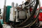
WET KIT STYLE - POWER PACK
1.0 DESCRIPTION
Supplied with this unit for installation by S&S on a suitable tractor with fifth wheel attachment will be a wet kit style hydraulic power unit. This unit is designed to transfer power from the tractor engine to the CTU hydraulic system. This wet kit power pack will be supplied on a single-square tube-frame assembly, which is pinned on the rear of the tractor. Power is transferred via a power splitter box and drive shaft to a two (2) place pump drive assembly.
Details of this system are as follows:
2.0 HYDRAULIC SYSTEM
A. MAIN HYDRAULIC SYSTEM
The injector is powered by a bi-directional, axial piston, pressure compensated, closed loop hydraulic pump system mounted on the output of the hydraulic drive gearbox. The injector brake control will be powered by primary drive pressure of this hydraulic pump system.
B. AUXILIARY HYDRAULIC SYSTEM
A tandem axial piston, pressure compensated hydraulic pump mounted on the second outlet of the hydraulic drive will provide for the following:
- Levelwind override hydraulic motor
- Levelwind lift control hydraulic cylinders
- Primary reel drive
- Hose reel hydraulic motors
- Control cabin lift cylinders
- Auxiliary outlet for an auxiliary spooling reel
- BOP rams
- Stripper/packer
- Injector chain traction system
- Injector chain tension
Note: The above hydraulic systems will be controlled by proportional control valves with built in directional and flow control functions and inlet relief valves.
C. HAND PUMP SYSTEM
Installed in the control cabin will be a high-pressure hand pump to provide back up power to the following:
- BOP rams
- Stripper/packer
- Injector chain traction system
D. ACCUMULATOR SYSTEM
Four (4) high-pressure accumulator bottles with a minimum volume of ten (10) US gallons per bottle will be supplied and installed to provide a constant back up hydraulic pressure to the hand pump system.
This accumulator system will be charged to 1500 psig from the above-described main hydraulic system and will be installed on the wet kit power pack.
E. HYDRAULIC OIL FILTRATION
All hydraulic oil circuits will include suction line filters with 100 mesh elements to remove particles. Elements will be removable for inspection and cleaning. Filtration of returning oil flows from injector and reel circuits immediately prior to entering main hydraulic tank will be carried out with the required filter assemblies. Filter size will not be less than 10 micron and will be spin on type. High-pressure filters will be installed to protect injector motors and pump. All filters will be fitted with a self- activating bypass valve and an indicator to show relative state of fouling of element.
Also supplied will be the other main components for a hydraulic system:
- A hydraulic oil reservoir with sight level gauge, filter breather cap, and return filters.
- A hydraulic oil cooler
- All necessary hydraulic valves, gauges, hoses, and piping
- A quick disconnect panel connected to the above system with outlets for extended connections to the tubing reel and the control cabin and hose reel assemblies.
3.0 TRUCK INSTALLATION KIT
Supplied with this unit will be the following items for installation of this wet kit on the tractor assembly. - Cushman Power splitter box assembly with pneumatic engage/disengage
- Drive shaft from splitter box to pump drive
- Anti-vibration mounts
- Driveline Modifications
4 GENERATOR
5 Mounted with the wet kit shall be an Onan CMQD 5000, 5kw generator (or equivalent). This generator shall be used to provide electrical power to the unit at the wellsite.
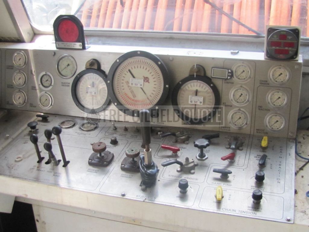
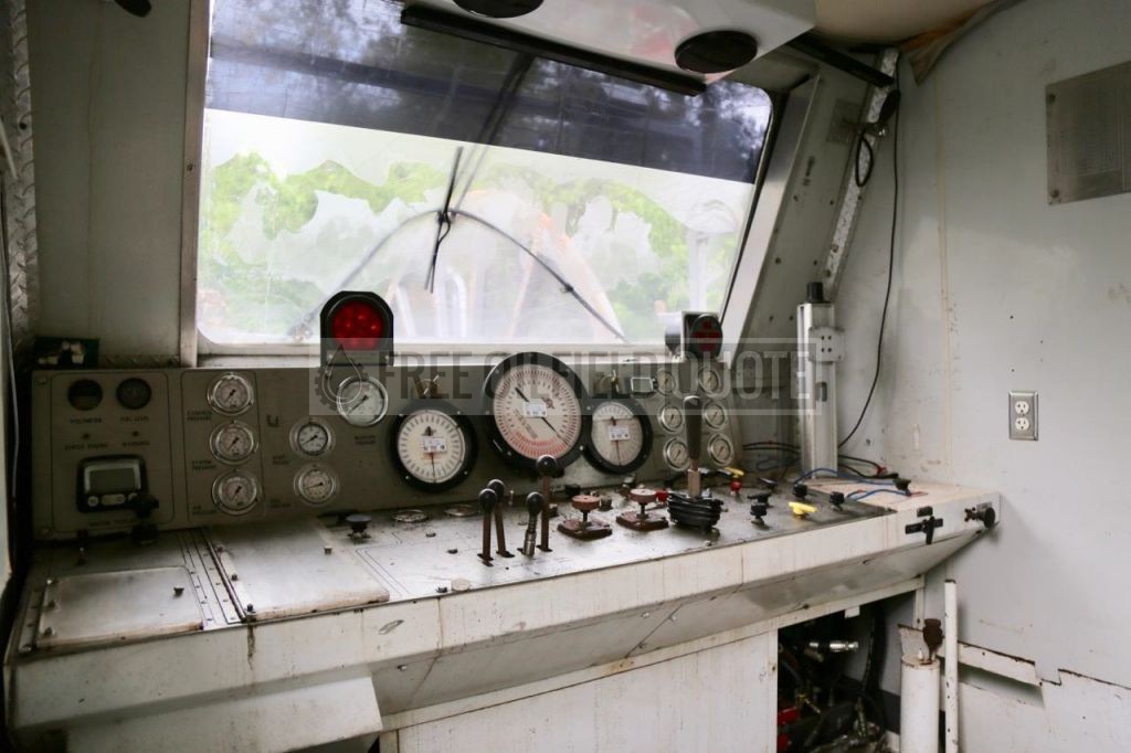
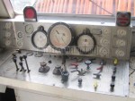
CONTROL CABIN
1.0 DESCRIPTION The unit will be fully operational from this new enhanced control cabin via mechanical, hydraulic, and pneumatic controls. The only exceptions to this will be the cabin lift system and the power hose reel controls, which are operated from locally sited controls. The new enhanced control cabin will be approximately 7’ wide x 10’ deep x 6’-6” high. It will be lined and fully insulated. The cabin will have two (2) side locking doors with windows and a large front window and with attack proof glass. The front window will be equipped with a windshield wiper and sun visor. Supplied and installed for access to the side doors of this cabin will be access ladders with grab handles.
Standard equipment in the control cabin will be:
- Stainless steel hardware - Internal LED and puck type lighting system
- Rolling Captain’s chair behind control console - Heavy-duty rubber insulated floor covering, fire resistant. - Two (2) stadium style seats at rear of cabin
- Air horn - Bard electric A/C and heater system
- Two (2) work lights (adjustable from cab)
- All hydraulic connections to and from the control cabin will be via a hydraulic bulkhead.
- Stewart & Stevenson installs an air driven pump in the cabin that can be used to deliver 5,000 psi to the stripper in case of emergency. This pump shall also have a handle instead and be used as a second manual back-up pump.
- A full control console will be installed in this cabin. This console will be of stainless steel construction and be fully labeled with all gauge and control information. The panel will be mounted on an engineered fabricated housing that incorporates the back-up pump, hydraulic valves, interface, etc.
- The following controls and gauges will be installed in this control console.
° Engine tachometer
° Engine throttle
° System air pressure gauge - fluid filled
° Engine stop button
° Engine emergency kill (if equipped)
° Oil pressure gauge
° Water temperature gauge
° Fuel level gauge
° Hydraulic oil level gauge
- Injector controls:
° In/out control valve (direction)
° Speed control
° Variable speed control
° Chain/gripper control valves with individual pressure gauge
° Chain tension control valve with individual pressure indication
° Chain tension control
° Injector drive pressure gauge - fluid filled
- Auxiliary system hydraulic pressure gauge - fluid filled
- BOP ram/auxiliary control valves – quantity of six (6)
- BOP safety control valve
- Hose numbers corresponding to each BOP control function will be labeled in panel
- Stripper packer hydraulic control valve and pressure gauge – quantity of two (2)
- Stripper window control
- Well head pressure gauge
- Circulation pressure gauge
- Tubing weight indicator
- Tubing reel tension (speed) control valve
- Tubing reel direction control
- Reel pressure gauge - fluid filled
- Inhibitor control
- Light switch
- Plus other miscellaneous gauges and controls for full operation of the unit
- Installed at side of control panel will be two (2) hydraulic hand pumps with auxiliary hydraulic reservoirs
- Installed in the cabin will be a separate hydraulic circuit for the injector load cell indicator
- External 110VAC outlet
- Sensor bulkhead
- Fold down desk near operators console
- AM/FM/CD Stereo system w/ speakers - A chart recorder will NOT be included
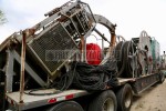
SERIES M-100L INJECTOR HEAD
1.0 DESCRIPTION
- This new unique Stewart & Stevenson M-100L (Long) Series Injector Head has the following patented features and general specifications:
2.0 EQUIPMENT
- Model No. : Series M-100L
- Length : 52”
- Width : 52”
- Height : 96”
- Weight : 8,500 Lbs. (excluding 90” Gooseneck) Pull Force High (working) : 100,000 Lbs.
- Snub Force : 40,000 Lbs.
- Max Speed : up to 200 ft/min.
- Speed @ 30,000 lbs Pull : up to 190 ft/min (+/-5%) Chain Type : Varia-Block III Heavy
- Gooseneck (Flared) : Two (2) Piece, 90” Hydraulic Folding Motors : Two (2) Axial piston, variable displacement
3.0 TOP DRIVE/BRAKE SYSTEM
- The top drive/static brake assembly consists of two (2) variable displacement, axial piston hydraulic motors, double reduction planetary gear reducers, and spring applied, pressure released, multi-disc brakes. These assemblies are flange mounted to the injector body and drive the carburized drive sprockets and timing gears.
- The drive motors are protected by high-pressure filters with reverse flow check valves. Each filter will have a 10 micron, stainless steel, and cleanable element.
- Hydraulic load holding counterbalance valves are installed at the motor ports to hold the tubing load (in and out hole) when the brakes are released.
4.0 DRIVE CHAIN DESCRIPTION
- Steel plate body construction with full access side openings to enable easy removal of the drive chain and tubing blocks.
- The drive chains and injector blocks may be fitted for tubing sizes of 1” OD through 2- 7/8” when fitted with the Varia-Block III chains.
- The traction chains are designed to transmit a force of not less than 100,000 Lbs. in the out-hole and 40,000 Lbs. in the in-hole directions from a stalled position. Slippage of the tubing relative to the gripper blocks will not occur at pulling force of 100,000 Lbs. with the surface of the tubing and blocks in a diesel wet condition. The force exerted by the chains on the tubing will not mark the surface of the tubing.
- The two (2) drive chains are of the roller chain type with connecting links to allow for replacement of the drive chains and injector blocks while the tubing remains in the injector.
- Separate connecting shafts connect the tubing blocks to each of the drive chains instead of the more common single through shaft, which causes adverse stressing of the tubing blocks in the case of misalignment of the drive chains and coiled tubing.
- Clearance between the tubing blocks when fully retracted allows for the passage of the various tools that are normally used in coiled tubing strings. The feature also allows easier tubing stab-in into the injector.
- The tubing blocks are the new Varia-Block III design. The new design incorporates a longer contact area per block to maintain contact with two (2) roller bearings at all times, and as many as three (3). The new design reduces wear, prolongs life, and should significantly reduce overall maintenance costs of the injector head and some of its parts
5.0 CHAIN TRACTION SYSTEM
- Chain traction is achieved by the use of a single skate/roller bearing assembly that applies pressure to the backsides of both drive chains. These roller assemblies are each compressed by single hydraulic cylinders. The 10 (10) hydraulic cylinders are plumbed in two (2) sets of five (5) hydraulic cylinders. If a failure in the hydraulic cylinders or tubing occurs, one (1) set can be isolated from the other and traction maintained on the tubing. Each hydraulic circuit incorporates an accumulator to prevent variations in tubing diameter to vary the hydraulic pressure. Each control circuit is protected by a velocity fuse to prevent loss of control due to hose failure. The two (2) sets of five (5) hydraulic cylinders have one (1) pressure control at the panel since the 10 (10) hydraulic cylinders operate at the same hydraulic pressure. This tubing traction system drastically reduces the tubing damage that is normally associated with excessive roller skate assembly hydraulic pressure.
- The roller skate assemblies use large 2-3/8” diameter roller bearings. The use of these large roller bearings with the new chain and block design ensures that two (2) rollers are in contact with each tubing block prior to transition from one (1) bock to the next at all times. This feature prevents pivoting and clattering of the tubing blocks as they pass over the drive chain sprockets and reduces the stress on the tubing caused by the gripping of the tubing blocks on the tubing. The tubing roller bearings are equipped with full lip
- seals for greater grease capacity and sealing capability and use large rollers with increased load ratings.
6.0 CHAIN TENSIONING SYSTEM
- Chain tensioning is achieved by a direct vertical movement of the bottom drive chain idler sprockets by two (2) pairs of hydraulic cylinders powered by a single hydraulic circuit with back-up accumulator for ease of operation. This feature gives a greater range of drive chain tensioning without reducing the drive chain contact on the drive chain drive and idler sprockets and thus increases the life of the drive chains.
7.0 TUBING GUIDE GOOSENECK
- The Heavy-Duty Tubing Guide Gooseneck is a 90” radius with steel roller straightener lower section and steel rollers on upper section. All bearings with grease zerts.
- Gooseneck will fold downward for storage by means of a hydraulic cylinder. The cylinder will also act as the stiffener for the tail section of the gooseneck.
- Heavy-duty pins and hinges on gooseneck.
8.0 GENERAL
- The injector pivots on one (1) side of the injector frame base, a load cell sensor is installed on the other side of the injector. The pivot bearings are lubricated.
- The injector is installed in an outer lift frame with steel base, guards, and a four (4) point lifting system, access ladders, and decking of the top of the protection frame.
- The injector is equipped with a bottom flange connection and adapter for use with a customer furnished 3.06 15M TOT Over/Under stripper/packer assembly.
- Compression cylinder piping is done in all stainless steel tubing to lesson the likelihood of a control line rupture on location.
- Velocity fuses are provided in the control circuit lines to prevent loss of control in the event of line failure. Fuse reset valves are provided for each circuit.
- All hydraulic connections on the injector are piped to a quick disconnect coupling panel, using bulkhead fittings installed at the bottom front side of the injector. All hoses will be supported by chain and hook arrangement so that hose connections do not carry a heavy load.
- Drain in bottom of drain pan, 1-1/2 NPT.
- Dual Hydraulic/Electronic load cell attachments
- Safety belt hooks at top of injector, recessed below plate.
- Chain attachment padeyes on top four (4) corners of frame, directed inward. Automatic brake release with injector motor pressure.
HOSE REELS AND HOSES
1.0 DESCRIPTION
Installed on the trailer package will be the following hose reel and hose assemblies:
2.0 TUBING INJECTOR POWER HOSE REEL
This will be a two (2) section hose reel hydraulically powered through a chain drive speed reducing arrangement with locally operated direction and speed control valve. This reel will be supplied with bearing and shaft retainers and incorporates a mechanical lock to hold the reel when not in use. This reel is used to hold the two (2) injector power hoses and is equipped with high pressure hydraulic hose swivels and Snaptite (or equivalent) type quick disconnect couplings.
2.1 HOSES
Supplied with each unit will be the following hose assemblies:
Installed on the Tubing Injector Drive Hose Reel will be the following hoses:
- One (1) set of 1-1/2” x 125-ft. long injector drive hoses with quick coupler assemblies
3.0 CONTROL HOSES – FIGURE 8 HOSE RACKS
BOP, injector and stripper control hoses will be installed on two (2) figure 8 hose racks mounted at the rear of the trailer:
- One (1) only set of 125 ft. long injector control hoses complete with quick coupler assemblies. This bundle will include the injector load cell hose. An electrical cable to connect the electronic load cell will also be part of this bundle.
- Two (2) only sets of 125 ft. long stripper packer control hoses complete with quick coupler assemblies bundled with injector control hoses.
- Six (6) only sets of 125-ft. long BOP actuator hoses, one (1) for each BOP ram assembly (i.e., pipe ram, slip ram, shear ram, blind ram, and two auxiliaries) complete with quick coupler assemblies. This bundle will include the wellhead pressure signal hose.
- Control hoses will be covered with Cordura (or equivalent) protection covering.
UNITIZATION & COMPLETION
1.0 DESCRIPTION
Supplied with the unit will be the following standard equipment. (Note: This equipment will be part of above unit, and if already mentioned, an item will not be duplicated.)
- Decking on the unit (where required)
- Installation of observation lights for 24-hour use
- Installation of all other electrical systems
- Installation of all pneumatic systems
- Installation of all hydraulic systems
- All steel and misc. fittings to complete the unit
- All labor to complete the unit
- Fire extinguisher
- General workmanship will be of good quality and appearance.
- Snaptite 72 Series quick disconnects are to be used.
Unitization and completion shall include but not be limited to the following:
- Flame cut edges shall be ground smooth.
- Sharp corners and edges to which operators and mechanics are vulnerable shall be ground smooth.
- Bolt holes for bolts shall be drilled (not torch cut) no mote than 1/8” larger than the bolt it accepts.
- Welds are of good quality and sufficient strength.
- Use self-locking nuts where applicable.
- No sweated or brazed type hydraulic fittings will be used.
- All hoses and connections will be within protective frame and be well secured rubber sleeves to prevent rubbing by frame, etc.
- Hydraulic reservoir to be constructed of steel plate with sight level gauge, cleanouts, vent, fill cap, etc.
The priming and painting of the equipment to be the customer’s color per Stewart & Stevenson’s standard paint specification, ES-502, latest revision
- Complete testing of equipment at Stewart & Stevenson plant in Houston, Texas, USA. Two (2) copies of all relevant test and quality control certificates of the manufacture and testing of all unit functions and parameters will be supplied together with two (2) copies of all required vendor and manufacturer test certificates in the English language.
- The unit will also be taken to a local test well to test the functionality under normal loads. S&S will provide two technicians for the testing. Testing will be complete when the unit has met contract specifications. Pipe for the test well test will be provided by S&S.
Important Buyers Notice: All items are Sold "As-Is" with "No Warranty" expressed or implied. Items offered for sale may be damaged, inoperable and/or missing parts. You are strongly urged to carefully review each photo and video as well as personally inspect the item before making a decision to purchase. Free Oilfield Quote is not responsible for any missing or damaged equipment, part, item or accessory and shall not be held liable for any damage prior to or during the removal and/or delivery of the equipment. Any and all agreements contrary to the above disclaimer must be in writing and agreed upon up front and prior to any transaction.